Electromagnetic Fault Injection – Part 1
Motivation
A few months ago I fiddled around with the inner workings of a printer. I thought it would be pretty funny to display my own images on the touch display. So naturally I tried reading the firmware off of the STM8 microcontroller that was on the display PCB. I quickly realized that you can’t read the firmware off of the chip because of the internal read-out-protection mechanism.
When searching for ways to bypass this, I came across fault injection attacks. Typically the goal of these attacks is to change the control flow of the program running on a microcontroller by introducing faults. This can be achieved in multiple ways, but most of the attacks require the attacker to physically modify (or even destroy) the device under test.
For example with voltage glitching you often have to remove capacitors from the PCB to make the glitch work1. With laser fault injection you have to either etch the chip with toxic chemicals or grind away the epoxy of a chip to expose the die2.
However with electromagnetic fault injection (EMFI) you don’t even have to touch the chip you are trying to glitch (this is a little bit exaggerated of course). The attack works by generating a strong electromagnetic pulse (at a very specific position) that induces a current in the chips circuit3. If successful the program skips an instruction, which can cause the chip to ignore a set read-out-protection bit, for example.
The problem is that commercial products for EMFI (like the ChipShouter or the ChipWhisperer) are pretty expensive, especially for a poor student like me. So, I decided to build my own low-cost EMFI setup.
High Level Overview
My EMFI setup consists of three parts
- A injection tip to produce high-intensity electromagnetic fields
- A XYZ-stage to accurately position the injection tip
- A device that triggers the glitch
Luckily I don’t have to design my own pulse generator as there is already a cheap open-source project that does just that. It’s called ChipSHOUTER-PicoEMP.
In this part I will document the process of building the PicoEMP and designing an adapter for the XYZ-stage.
Building the PicoEMP
PCB
As the project is open-source I just downloaded the gerber files for the PCB and uploaded them to JLCPCB. The order cost around 7 euros and arrived after 12 days.
BOM
The bill of materials is nicely explained on the github page of the project. Although the BOM wasn’t updated in over 4 years. Most of the parts were still available on DigiKey. For many components, I ordered spares in case I dropped or damaged them while soldering. I bought the SMA connectors on AliExpress as they are ridiculously expensive on DigiKey. (Click here if you want to see what components I ordered in what quantities.)
Build
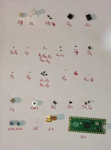
The build process was pretty straightforward. I laid out all the needed components on a sheet of paper and wrote their corresponding reference designators below them, so I only had to search for components once and not all the time.
The only problem I had when assembling was that the diode D7 doesn’t have any markings on it to indicate its polarity. The build instructions on github also said that its crucial to get the polarity right, otherwise Q2 may blow up. So I had to check the polarity with a multimeter, then remember it correctly and solder it on.
Another problem I had (out of pure laziness) was that I soldered the LEDs on in the wrong orientation. When trying to desolder them, I broke one. I didn’t have any 0603 LEDs left, so I searched around the house and found a dead router which happened to have 0603 LEDs, so I quickly desoldered them and gave them new life in the PicoEMP.
After the LED transplantation was done I turned on the device. Luckily, no magic smoke appeared.
Now enjoy me soldering the board for around 40 minutes in 38 seconds!
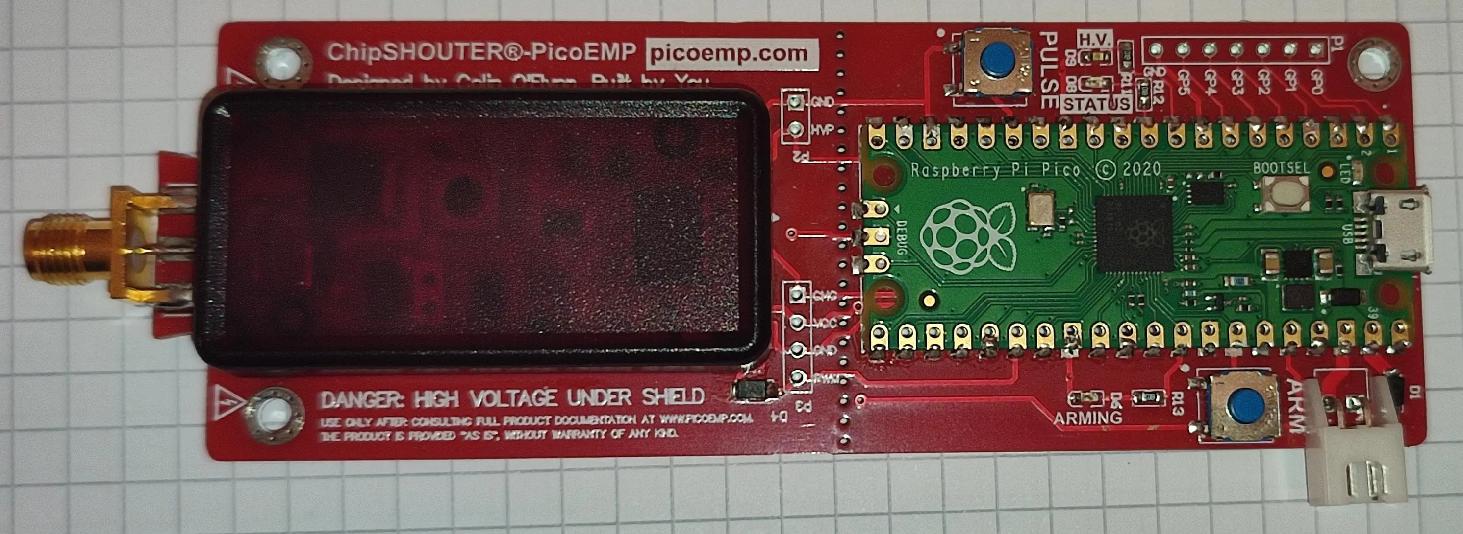
The finished board looks like this:
Flashing
Flashing the firmware was as easy as connecting the pico to my laptop and copying the .uf2 file, from the releases page over to the pico.
Building an Injection Tip
To test and use the PicoEMP I need an injection tip first. So, I took one of the ferrite rods I ordered and put a few turns of coated copper wire around it to create a coil. Then I soldered the wire ends to the SMA connector and put some heatshrink around everything.
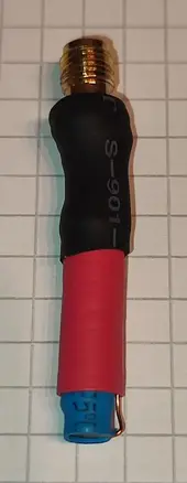
I want to point out here that I have no idea what characteristics this coil has and how suitable it is for fault injection!
First Test
Before watching the video below make sure to first read the description of whats happening, otherwise the video won’t make any sense to you!
I chose an ATmega 328P development board as a target because that was the first microcontroller I found in my drawer. I programmed the microcontroller so that it flashes the yellow LED in a 1 second on, 1 second off cycle. Forever. So we know something is off if it behaves differently.
Next I take the PicoEMP and press the ARM button. The red LED lights up indicating that it is now charging the high voltage capacitors. Shorty after, the second green LED on the left side of the board lights up, indicating that the capacitors are now fully charged (hard to see in the video).
With about 5mm distance between injection tip and chip I hover right over the ATmega chip and press the PULSE button. The first try at second 17 to 18 in the video didn’t work; the yellow LED still flashes. However the second try between second 20 and 21 succeeded. The yellow LED is now constantly on for the rest of the video!
This means that the device works!
Preparing the XYZ-Stage
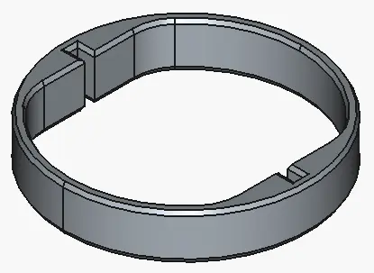
To mount the PicoEMP on my small CNC mill I designed a small ring structure in FreeCAD that holds it in the mills tool holder.
Fully assembled the contraption looks like this:
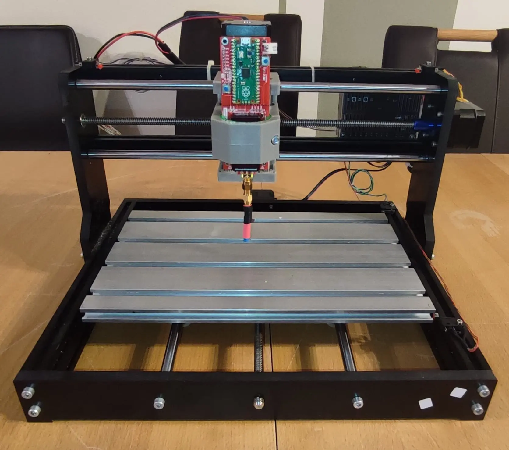
With this setup I can now precisely control the position of the PicoEMP in X, Y and Z direction.
Now the only part missing is a device to reliably trigger the glitch.