byu25 - alpha
Overview
- CTF: BYUCTF25
- Challenge name: Alpha
- Author: deltabluejay
- Category: embedded
- Difficulty: medium
- ctf files: alpha_REDACTED.ino, flag.sal
Challenge description
I made a little Arduino program that displays a flag on a 14-segment display! I captured the I2C data sent to the screen using my Saleae logic analyzer… can you decipher it and extract the flag?
Recon
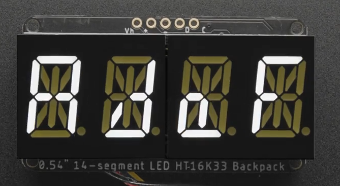
The description links to the Quad Alphanumeric Display from Adafruit. This is a 4-character, 14-segment display capable of showing digits 0-9, characters a-z and A-Z and decimal points1. Some characters are pretty hard to read in my opinion.
The characters are written to the display using i2c, which is common a two-wire serial communication protocol. The two lines are called SDA (serial data line) and SCK (serial clock line). i2c allows multiple devices to be controlled over the same bus, with each device identified by an unique address2.
The challenge provides two files:
alpha_REDACTED.ino: Arduino code that first initializes the display (in setup()) and then sends the characters of the global flag variable in a scrolling animation (in loop()), to the display (presumably over i2c). The actual flag is redacted.
#include <Wire.h>
#include <Adafruit_GFX.h>
#include "Adafruit_LEDBackpack.h"

Adafruit_AlphaNum4 alpha4 = Adafruit_AlphaNum4();

String flag = "byuctf{REDACTED}";

void setup() {
  Serial.begin(9600);
  alpha4.begin(0x70);
  alpha4.writeDigitRaw(0, 0x0);
  alpha4.writeDigitRaw(1, 0x0);
  alpha4.writeDigitRaw(2, 0x0);
  alpha4.writeDigitRaw(3, 0x0);
  alpha4.writeDisplay();
}

void loop() {
  delay(1000);
  for (uint8_t i = 0; i < (flag.length() - 3); i++) {
    alpha4.writeDigitAscii(0, flag[i]);
    alpha4.writeDigitAscii(1, flag[i+1]);
    alpha4.writeDigitAscii(2, flag[i+2]);
    alpha4.writeDigitAscii(3, flag[i+3]);
    alpha4.writeDisplay();
    delay(500);
  }
}
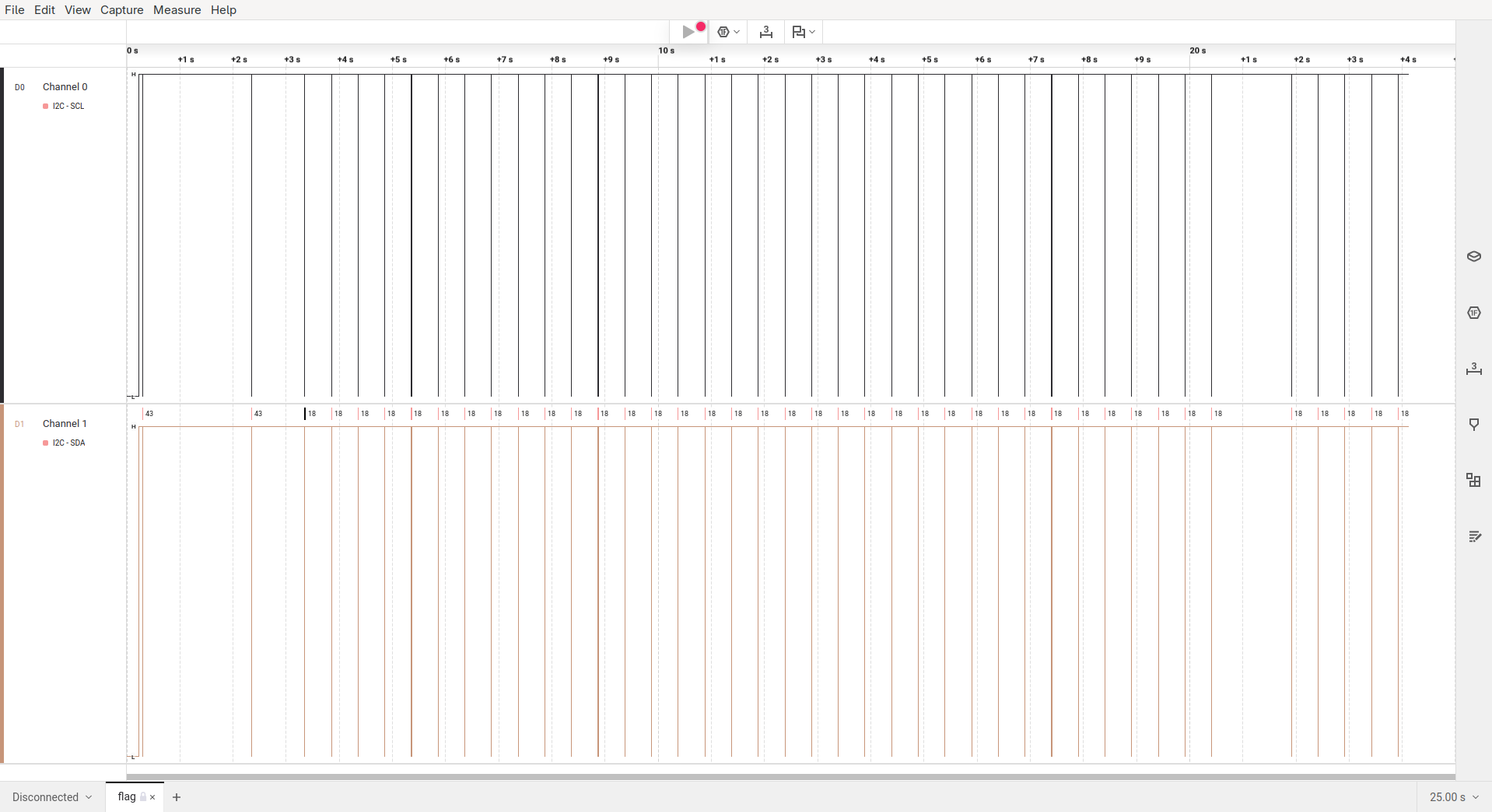
flag.sal: A capture file from a Saleae logic analyzer. These devices are pricey (please buy me one!), but their software, Logic23, is free to use in demo mode.
Opening the file in Logic2 we see that the SCL and SDA data lines were captured (which were used to transmit the flag). Also the capture is about 25 seconds long, which you can see in full below.
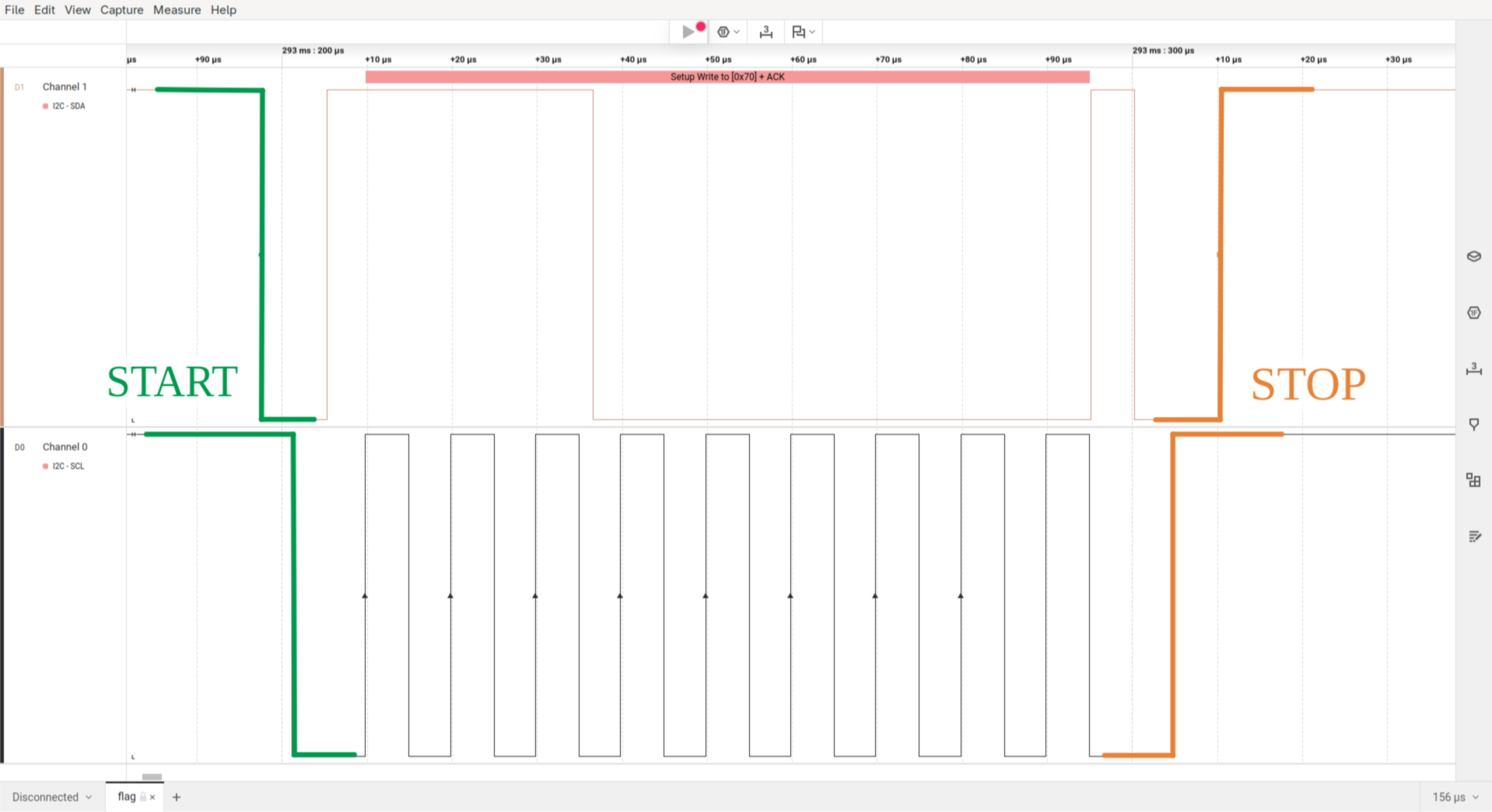
To have a look at the actual data that is being transmitted you have to zoom in pretty far. As you can see below, the pulses on the SCL line are only 5 microseconds short!
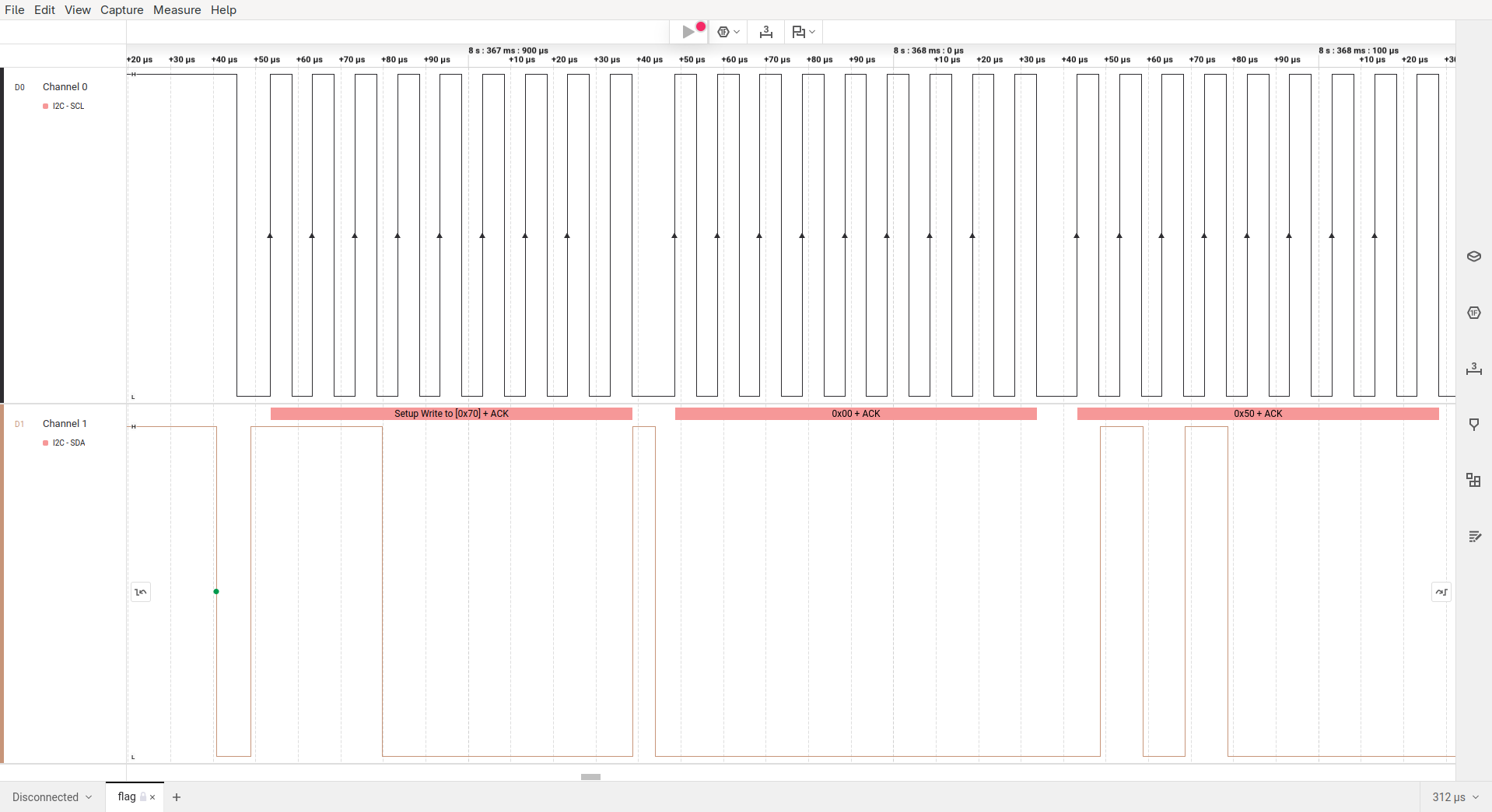
That said, there’s still a lot of ground to cover before we can start making sense of this capture. So let’s dive in and reverse engineer the flag!
ASCII representation
Initially, the capture file doesn’t contain anything that I could immediately identify as ASCII characters. To understand how characters are encoded, we examine the source code for writeDigitAscii4.
The functions signature in Adafruit_LEDBackpack.h tells us that the function actually has three arguments:
- The digit position
n(0-3) - The ASCII character
ascii - An optional flag that sets the decimal point (default =
false)
/*!
    @brief  Write single ASCII character to alphanumeric display.
    @param  n      Character index (0-3).
    @param  ascii  ASCII character.
    @param  dot    If true, also light corresponding dot segment.
*/
void writeDigitAscii(uint8_t n, uint8_t ascii, bool dot = false);
In the functions implementation in Adafruit_LEDBackpack.cpp we see that our character a is looked up in alphafonttable and then fed into the pgm_read_word function, which is used to read data from the flash memory of a microcontroller. The resulting data is then stored in displaybuffer[n].
void Adafruit_AlphaNum4::writeDigitAscii(uint8_t n, uint8_t a, bool d) {
  uint16_t font = pgm_read_word(alphafonttable + a);

  displaybuffer[n] = font;

  /*
  Serial.print(a, DEC);
  Serial.print(" / '"); Serial.write(a);
  Serial.print("' = 0x"); Serial.println(font, HEX);
  */

  if (d)
    displaybuffer[n] |= (1 << 14);
}
The alphafonttable is an array (stored in flash memory) with 128 values of 16 bit each. The first 14 bits control the character’s segments; bit 15 is for the decimal point, and bit 16 is unused. So each of the 128 ASCII characters has a bit representation. Some of the none-printable characters are also mapped. For example \x1B maps to 0b0000000011100011, which could represent the degree symbol °.
static const PROGMEM uint16_t alphafonttable[] = {
...
  0b0000000000000110, // !
  0b0000001000100000, // "         Bit/Segment mapping:
  0b0001001011001110, // #
  0b0001001011101101, // $         -------0-------
  0b0000110000100100, // %         |\     |     /|
  0b0010001101011101, // &         | \    9    / |
  0b0000010000000000, // '         |   8  |  10  |
  0b0010010000000000, // (         5    \ | /    1
  0b0000100100000000, // )         |     \|/     |
  0b0011111111000000, // *         |--6---|--7---|
  0b0001001011000000, // +         |     /|\     |
  0b0000100000000000, // ,         4    / | \    2
  0b0000000011000000, // -         |  11  |   12 |
  0b0100000000000000, // .         | /    13   \ |
  0b0000110000000000, // /         |/     |     \|
  0b0000110000111111, // 0         -------3-------  14
  0b0000000000000110, // 1
  0b0000000011011011, // 2        0b 0000 0000 1110 0011
  0b0000000010001111, // 3        0b 0001 0010 1111 1001
...
Now we know that writeDigitAscii stores a character’s bit-representation into displaybuffer.
Writing to the Display
After the four calls to writeDigitAscii in alpha_REDACTED.ino we see another function, named writeDisplay. The source code tells us that this function writes every value in displaybuffer (uint16_t = 2 bytes!) to buffer. It is important to note here that the values from displaybuffer are stored in little-endian format to buffer as the least significant byte (displaybuffer[i] & 0xFF) comes first in buffer.
After every value from displaybuffer has been processed, the contents of buffer are sent to the display over i2c with i2c_dev->write.
void Adafruit_LEDBackpack::writeDisplay(void) {
  uint8_t buffer[17];

  buffer[0] = 0x00; // start at address $00

  for (uint8_t i = 0; i < 8; i++) {
    buffer[1 + 2 * i] = displaybuffer[i] & 0xFF;
    buffer[2 + 2 * i] = displaybuffer[i] >> 8;
  }

  i2c_dev->write(buffer, 17);
}
Extracting the flag
To identify the little-endian flag characters in the capture file I wrote a script that prints out all character bit representations in hexadecimal little-endian representation5.
! 0600
...
b 7820
c d800
d 8e08
e 5808
f 7100
...
t 7800
u 1c00
v 0420
w 1428
x c028
y 0c20
z 4808
{ 4909
...
We know that the flag starts with byuctf{. Translating the characters with the above table we get the following bytes.
|   b   |   y   |   u   |   c   |   t   |   f   |
|-------|-------|-------|-------|-------|-------|
| 78 20 | 0c 20 | 1c 00 | d8 00 | 78 00 | 71 00 |
Now we can search for these bytes in the capture file.
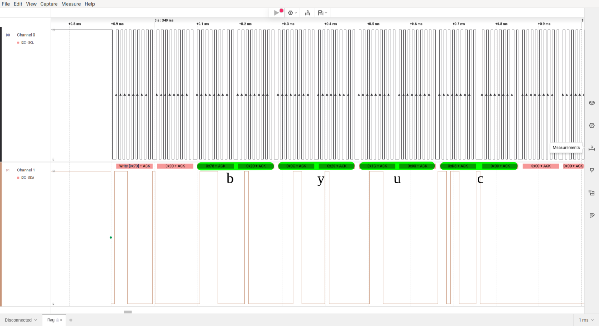
As the program does a scroll animation to display the flag we can always skip three data frames to extract the full flag.
read: byuc
skip:  yuct
skip:   uctf
skip:    ctf{
read:     tf{4
...
The extracted flag is: byuctf{4r3n7_h4rdw4r3_pr070c0l5_c00l?}
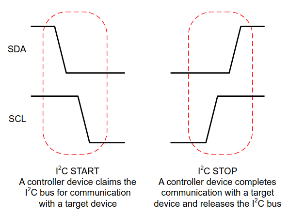
More on i2c
The following part has nothing to do with challenge itself.
While writing this writeup I got interested in the i2c protocol and how it really works. I already used it quite often in personal projects but don’t really know how it works. Let’s change that to some degree.